


rkruz
-
Posts
16 -
Joined
-
Last visited
-
Days Won
2
Everything posted by rkruz
-
you found a replacement switch? I could not find a replacement.
-
As a light board switch replacement alternative. You should verify your switch is bad before doing anything as the switch is the least likely of anything to fail. If both banks of lights are not working there may be something else wrong probably with the power to the light board. When toggling the switch, If one bank of LEDs work, its likely the switch is bad. To verify the switch is bad, with the machine off, use an ohm meter and measure across the terminals in the attached picture with the red line. The measurement should be 0 ohms when the switch is set for the white LEDs and infinite ohms when in the center or UV LED selection. Toggle the switch left and right positions and if you never see 0 ohms than the switch is bad. To bypass the switch: If your sure the light board switch is bad as verified above, rather than replace the switch, it would be very easy to solder a small wire on the back of the board to 2 of the switch terminals, bypassing the switch and turning on the white lights permanently. The attached photo shows where this location would be. The only drawback is the lights would be always on whenever the machine is turned on. Also, depending on how the switch failed, its possible selecting the UV switch setting would turn those LEDs on at the same time as the white LEDs which is not a big deal unless you only want the UV LEDs on for as I said, the white LEDs will be permanently on with this mod.

-
I dont sorry. It a common switch and would be easy to find a replacement. Alternatively, rather than replace the switch, you could just hardwire across 2 terminals on the switch that activate the white lies, solder a wire to them and it would be on all the time. Solder a small wire across the switch terminals that activate the white LEDS. To find a replacement, search for : Toggle Switch, ON-OFF-ON, PCB Mount, Right Angle. and then make sure the body size and number of contacts and spacing is the same. Ebay would have one. If I get a chance later Ill pull the board and see what is installed and look for a replacement.
-
"From Cagey: Would it be possible to figure out which of the four individual LEDs is burned out on the four sectors?" How to identify the bad LED: The circuit design is such that if one LED goes out, a bank of 3 LEDs will go out, like Christmas tree lights. These 3 LEDs are all next to each other. Once the board is removed and unplugged, its a simple matter to identify the bad LED using a Digital Voltmeter (DVM). With the DVM set for the lowest ohms range, or using the diode check function, place the DVM probes across 2 of the 4 LED pins. You will have to do some experimentation to figure out the right pins with some trial and error. IF the DVM reads zero ohms those are the wrong pins and move one probe to one of the other pins. If still not lit then change the polarity of the probes or swap the red and the black probes. Once you know which pins to touch by seeing a good LED illuminate, then repeat on the other LEDs until you find one that will not. Dont worry, the DVM will not damage anything on this simple circuit.
-
The video is only for the installation of the LED, not the removal. The removal is the hard part. I found it was easiest just to break apart the bad LED plastic body with diagonal wire cutters leaving only the metal pins that are soldered in the board. Then grab the pins with needle nose on the component side of the board, and heat the pins with a soldering iron (25 watt tip) until the solder melts and pull the metal pin out leaving a feed-thru hole that still filled with solder. I then used a "solder sucker" or spring loaded suction device to remove the solder from the feed-thru hold by heating the feed-thru then using the solder sucker to extract the melted solder. A delicate and experience touch is needed here or you can pull the pad off the board. Once the feed-thru holes are open or clear of solder, the new LED just drops in and can be soldered as demonstrated in the video you provided.
-
I dont sorry. It a common switch and would be easy to find a replacement. Is there a part number or other clue printed on the switch.?. You could just hardwire across 2 terminals on the switch, solder a wire to them and it would be on all the time. Solder a small wire across the switch terminals that activate the white LEDS. A Search would be for : Toggle Switch, ON-OFF-ON, PCB Mount, Right Angle. and then make sure the body size and number of contacts and spacing is the same. Ebay would have one. If I get a chance later Ill pull the board and see what is installed and look for a replacement.
-
sorry. there is no attachment?
-
I purchased replacement LEDs from Ebay from a company called LighthouseLEDs.com. 20ea for $9 including shipping so about $0.45 each. I have already removed that bad LEDs and soldered the in these replacements and the brightness and light color are indistinguishable from the originals. The entire bank of 3 that were out are now working once the bad LED was replaced. The part number and seller info is in the attached photograph.


-
After a short search, Ive not found a specific LED replacement but made some discoveries that helps to narrow down the search and I am still looking for a LED replacement. In general the square LEDs appear to be in the $0.50 to $2.50 each. The LED board is very easy to remove. Loose 1 screw and slide the board out. A 3 position toggle on the board selects White, UV or OFF. There are no active components on the board, only LEDs, resistors and a toggle switch. The simplicity of the board again makes for a very easy low risk LED replacement. The white LEDs are connected in banks of 3. If one LED fails the entire bank fails. See the attached picture showing the white LED. In my case I have 4 LEDs failed hence a total of 12 LEDs not lit. With a DVM set in "Diode" mode, I can actually turn on individual LEDs installed on the board and have identified a single LED in each back that has failed. The LEDs themselves have no identification markings on them to help find a replacement. The white LEDs appear to be the style of 7.62mm square, using through hole wires and runs from 3VDC. The through hole wires along with the large solder pads make it a very easy LED replacement for someone mildly experienced using a soldering iron and solder wick or solder sucker. See the attached picture showing the leaded LEDs on the board. THE UV LEDs are a different style but none of these have failed. See the attached picture showing the UV bank of LEDs on. The board is marked with "APQS" so they should have the circuit card design to include the mfr and part numbers for the LEDs should they care to share that information. If I can obtain LED replacements I will create a "How To" video detailing how to replace the LEDs. As for my background I have 2 Masters Degrees in Electronics Engineering and 40 years of experience designing electronics and managing the development of high technology systems. Much my experience was performing detailed electronic design, which this board would be of the simplest example.


-
Several LEDs have failed in the under light assembly or LED board. See the picture of the board. Its a simple matter for me to replace the bad LEDs but I would need a mfr and part number. Not the UV LEDs but only the white light color LEDs is what have failed. APQS only sells the entire assembly for close to $200 which I cannot afford and the LEDs might be about $0.25 each which being an electronics engineer I have replaced before in a circuit card. Any hints here appreciated. Thank you . .

-

For Sale: Quilt-EZ Templates, 3 type, 8 qty, $160
rkruz replied to rkruz's topic in For Sale - Used Quilting Machines
One of the patterns, Clamshells have sold. The ad has been edited to remove them. -
For Sale: Quilt-EZ Templates, 3 type, 8 qty, $160
rkruz replied to rkruz's topic in For Sale - Used Quilting Machines
12ea refers to the quantity. There are 12 of them at $20 ea. -
For Sale: Quilt-EZ Templates, 3 type, 8 qty, $160
rkruz replied to rkruz's topic in For Sale - Used Quilting Machines
They are $20 ea plus shipping. The entire stack of 12 would take 2ea USPS Game Box to fit properly and would ship for $20ea. 10 templates or less would fit in a single USPS Game box. -
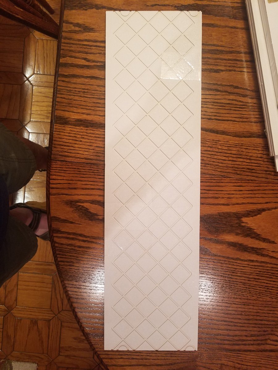
Quilt following templates from Quilt-EZ.com Follow the Grooves to a Perfect Pattern. Templates let any quilter create a perfect pattern. Follow the groove on the board and trace your way to an easier pattern. Each board is made of ABS plastic and is 3/16ths inch thick. The grooves in each board are 1/8th inch wide. These templates have never been used and in original wrapping. 3 patterns are provided: Crosshatch, 2 templates, T06-057A Open Swirl, 3 templates, T06-186A Open Meander, 3 templates, T06-180A $20 shipping anywhere in U.S.


-
For Sale: Baby Lock Serger, BLE8, Rarely Used, $700
rkruz replied to rkruz's topic in For Sale - Used Quilting Machines
ahhh, forgot. thanks for pointing that out. $700 -
$700 A Baby Lock BLE8 in like new condition. Rarely used. It will serge up to 8 threads simultaneously. Amazing threader uses air to route the thread. The cutter is razor sharp and makes a perfect edge. Many stitch types (23 in the quick start guide) and will interlock up to 8 threads. The machinery looks perfect internally, dust free and no evidence of use. It ran flawlessly during our test of it. We made a video of this test. See a video of it in action here. https://photos.app.goo.gl/bqU67KsMrR1nXiRu6 Includes manual, workbook, quick reference threading guide, machine cover, binding foot, threader and many tools. We prefer it be picked up here in Orange County, CA but we can ship for the shipping cost.


